 English
-
 Español
-
 Português
-
 Portugiesisch
-
 Français
-
 日本語
日本語
-
 Български
-
 한국어
한국어
-
 Türkçe
-
 Nederlands
-
 English
-
 Eesti
Eesti
-
 Suomi
Suomi
-
 বাঙ্গালি
-
 беларуская
-
 Ελληνικά
-
 Kreyòl ayisyen
-
 עִברִית
-
 हिन्दी
-
 Magyar
-
 íslenskur
-
 Gaeilge
-
 italiano
-
 Hrvatski
-
 Latinus
-
 latviski
-
 Melayu
-
 Malti
Malti
-
 Монгол
-
 မြန်မာ
-
 فارسی
فارسی
-
 Polski
-
 عربي
عربي
-
 Română
-
 русский
-
 slovenský
-
 Slovenščina
-
 Afrikaans
-
 svenska
-
 dansk
dansk
-
 український
-
 o'zbek
-
 Cymraeg
-
Zulu
-
 Tiếng Việt
-
 bosanski
-
 Deutsch
-
 eesti keel
-
 ไทย
ไทย

- How on earth is QR code recognized? How does the black and white cube store data?
- The co-inventor of the bar code has died, He's the one who changed the round size into zebra print
- Is the IP protection level of the bar code scanning gun as high as possible?
- Choose and buy Industrial bar code scanner, stable use is more critical
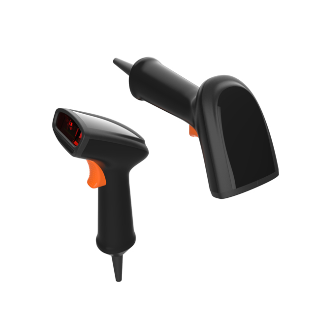
The laser barcode scanning gun principle, you must have been in contact with!
Tue Feb 28 10:50:17 CST 2023
Today, the optical application details are the principle and components of the laser barcode scanning gun, laser scanner is a kind of optical distance sensor, used for flexible protection of dangerous areas, through access control, access protection, etc. It has three scanning modes: single line scanning, raster scanning and full Angle scanning. Interested friends please read this article!
Laser bar code scanner has been widely used because of its unique advantages of large depth of field, high scanning speed and wide scanning range. In addition, the laser all-angle laser bar code scanner is widely used in various fields with high degree of automation and high material flow because it can scan and read the bar code symbols in any direction at high speed. The laser bar code scanner consists of laser source, optical scanning, optical reception, photoelectric conversion, signal amplification, shaping, quantization and decoding, which are discussed in detail below.
Principle of laser scanning gun
The laser scanning gun scans the bar code by the light source printed out, and identifies the bar code by the huge difference in the light reflected by the black and white bars of the bar code. When scanning a set of bar codes, the light source illuminates the bar code and the reflected light passes through the lens to the scanning module, and the scanning module (commonly known as the scanning gun decoding board) converts the optical signal into an analog digital signal (voltage). It is related to the intensity of light received). It can be transferred to the computer and that's what we want the bar code to be. In the process of the scanning gun from the acquisition of the light source to the decoding analysis into the computer input signal, if the bar code can not be correctly identified, the laser source line will always be bright, which is actually the scanning gun has been decoding process, if the decoding is successful, the laser line will be automatically extinguished.
The analog - digital converter circuit converts the analog voltage into a digital signal, which is sent to the computer. Color is quantized with 8, 10 and 12 bits of RGB, and the signal is processed into the image output of the above bits. A higher quantization number means that the image can have a richer layer and depth, but the range of colors is beyond the ability of human eyes to recognize, so in the range of distinguishable range for us, the higher digit scanning gun scanning effect is smooth color cohesion, can see more details of the picture.
Component of laser scanning gun
(1) Laser source
The visible light semiconductor laser manufactured by MOVPE (metal oxide gas phase epitaxy) technology has the advantages of low power consumption, direct modulation, small size, light weight, solid, high reliability and high efficiency. It quickly replaced the original use of He-Ne laser.
The beam emitted by the semiconductor laser is a non - axisymmetric elliptic beam. The divergence Angle V perp ≈30° is perpendicular to the direction of P-W junction plane, and the divergence Angle V‖≈10° is parallel to the direction of the junction plane. If the traditional beam collimation technique is used, the long and short axis directions of the elliptic spots on both sides of the beam converging point will be exchanged. Obviously this will give the scanner only a small depth of field.
Jay M. astman et al. proposed to use the beam collimation technology shown in Figure 3 to overcome this exchange phenomenon and greatly improve the range of scanning depth of field. This elliptical beam can only be used in single - line laser scanners. When arranging the light path, the long axis of the ellipse of the light spot should be perpendicular to the scanning direction of the light. For a single line laser bar code scanner, this elliptical spot will have better characteristics than the circular spot described below due to its insensitivity to printing noise.
For the full Angle bar code laser bar code scanner, because the beam in scanning the bar code, sometimes with a large Angle of inclination across the bar code. Therefore, the beam spot should not be oval. It's usually rounded into a circle. A common shaping method is to add a small circular aperture in front of the collimating lens. This beam property can be well approximated by Fresnel diffraction properties of small holes. With this scheme, the depth of field can be about 250mm to 300mm for standard size UPC bar codes.
This is sufficient for the average commercial POS system. But for the airport baggage line and other requirements of large depth of field, it is not enough. At present, the commonly used scheme is to increase the size of the bar code symbol or make the different scanning rays of the scanning pattern converge on different areas to form a "multi-focal surface". But a more attractive scheme is to use a special optical collimating element, through which the light field has a special distribution and thus has a very small beam divergence Angle, to obtain a large depth of field.
(2) Optical scanning system
The laser beam from the laser source also passes through the scanning system to form a scan line or scan pattern. Full Angle bar code laser bar code scanner generally adopts rotating prism scanning and holographic scanning two schemes. Holographic scanning system has the advantages of compact structure, high reliability and low cost. Since IBM's 3687 scanner was first used, it has been widely used and constantly updated. It is to be expected that its share of the market will grow.
Rotary prism scanning technology has a long history and is technically mature. It uses a rotating prism to scan the light beam and a set of folding plane mirrors to change the light path to achieve multi-direction scanning of light. At present, the scanner products such as MS-700 which are widely used also make the wedge angles of the different faces of the rotating prism different and form several scanning lines in one scanning direction. A high density scanning pattern is formed by multi-directional and multi-line scanning rays. Another possible benefit of this approach is the mitigation of laser radiation.
The concept of full Angle scanning was first proposed in order to increase the speed of supermarket circulation, and the corresponding UPC barcode was designed. For UPC code two scanning directions of the "X" scan pattern has been able to achieve full Angle scanning.
With the development of scanning technology, bar code application field broadening and improve the degree of automation of the urgent need, is now the concept of full Angle scanning to other code system, such as 39 code, intercalation 25 code. The bar code of these codes is relatively small in height and width, in order to achieve full Angle scanning will need much more scanning directions. In addition to the rotating prism, another moving element will need to be added, such as rotating the folded flat mirror group shown in Figure 4.
Because of the low scanning speed and small scanning Angle, there are many schemes that can be used for beam scanning. In addition to the use of rotating prism, pendulum mirror, but also through many parts of the motion optical system to achieve beam scanning. For example, beam scanning can be realized by moving semiconductor laser and moving collimating lens. In addition to the DC motor, the power components can also be piezoelectric ceramics and electromagnetic coils. These power components are not easy to damage, long life and easy to use, and it is estimated that they will be used in some extent.
(3) Optical receiving system
The scanning beam is scattered on the bar code symbol, and the receiving system receives enough scattered light. In the laser full - Angle laser bar code scanner, the backward-receiving system is widely used. In this structure, the main optical axis of the receiving beam is the outgoing optical axis. In this way the scattered light spot is always located on the axis of the receiving system.
The instantaneous field of view of this structure is very small, which can greatly improve the signal-to-noise ratio, but also improve the ability to suppress the mirror reflection of the bar code symbol, and the requirements for the receiving lens are very low. In addition, it can also make the sensitive surface of the receiver smaller. This is also important because the sensitive area of high-speed photoreceivers is generally small, and the cost of receivers with small sensitive areas is also low. Its disadvantage is that vignetting occurs when the scanning beam is located at the edge of each component of the scanning system. In addition to structural measures to minimize vignetting, scanning angles with poor characteristics should also be discarded.
The optical automatic gain control system is also widely used in the full-angle laser bar code scanner, so that the received signal light intensity does not change with the distance of the bar code symbol. This can narrow the dynamic range of the signal and facilitate subsequent processing.
The handgun laser bar code scanner has the characteristics of slow scanning speed and low signal frequency. Low response frequency receivers such as silicon cells have a larger sensitive area, and the low frequency system is easy to achieve a high signal-to-noise ratio. Therefore, in addition to the above backward receiving scheme, other schemes can be adopted. For example, the outgoing laser beam can be modulated at a higher frequency by the easy modulation of semiconductor laser. Then, the bar code signal is removed by synchronous receiving amplification technology when the electrical signal is processed. As long as the modulation frequency is much larger than the bar code signal frequency, the bar code width error brought by it will be negligible.
Synchronous receiving technology has high noise suppression ability, so it is not necessary to use the backward receiving structure. This will give considerable flexibility to the arrangement of optical receiving systems. Some aspects of the reader's performance can be improved by taking advantage of this flexibility. For example, in the backward receiving scheme, the moving element is also a part of the receiving system. It is required to have a certain aperture size to ensure that enough signal light can be received. However, if the moving element only acts as a scan for the outgoing beam, it can be done very small. Obviously small motion components for the selection of power components or to improve the life, reliability are extremely advantageous.
(4) photoelectric conversion, signal amplification and shaping
The received optical signal needs to be converted into an electrical signal by a photoelectric converter. The bar code signal frequency in the full Angle laser bar code scanner is several megahertz to tens of megahertz. Such high signal frequencies require the photoconverter to use an avalanche photodiode (APO) or PIN photodiode with high frequency response capability. Full Angle laser bar code scanner is generally used continuously for a long time, in order to user safety, the laser source is required to emit less energy. So the final energy received is very weak. In order to obtain a high signal-to-noise ratio (which is determined by the bit error rate), a preamplifier circuit composed of discrete components with low noise is usually used to amplify the signal with low noise.
Hand-held laser bar code scanners have signal frequencies of tens to hundreds of kilohertz. Generally, silicon photocell, photodiode and phototriode are used as photoelectric conversion devices. Handgun laser bar code scanner is relatively strong light energy, low signal frequency, in addition, as mentioned before can also use synchronous amplification technology. Therefore, it does not require very high characteristics of electronic components. And because the signal frequency is low, it can be more convenient to implement automatic gain control circuit.
Because of the edge ambiguity of bar code printing, mainly because of the limited size of the scanning spot and the low-pass characteristics of the electronic circuit, the edge of the signal will be blurred, often called "analog electrical signal". The signal must also go through the shaping circuit to recover the edge as accurately as possible, into what is commonly called a "digital signal". Similarly, hand-held scanners will have more scope for shaping because of their low signal frequency.
From the above mentioned situation, we can see that high signal frequency brings great technical difficulties and cost increases. For full-angle laser bar code scanner with certain reading ability, its data rate R is proportional to n/(H×Cos α-w ×sinα).
Where, n is the number of scanning directions, H and W are the height and width of bar code symbols respectively, α is the Angle value when the scanning pattern of bar code symbols is at the most unfavorable for scanning and reading. For the uniformly distributed scanning lines, α = π / 2n, for example, α is 45° when n = 2, we can estimate from this formula that for UPC code, If the scheme of scanning the left half and the right half and stitching is adopted, the data rate is the lowest when n is 3. For the scheme that can be read completely through the whole bar code, the data rate is the lowest when n is 5. This should be considered in the design of scanning system.
In addition, low speed scanning modules can also be combined into an array to achieve full Angle high speed scanning bar code performance. Obviously, this scheme is more suitable for application in pipeline situations.
(5) Decoding
After the reshaped electrical signal is quantized, the information contained in it is translated by the decoding unit. Because of the high data rate of the full-angle laser bar code scanner, and most of the obtained signals are non-bar code signals and incomplete bar code signals, the decoder needs to have the ability to automatically identify valid bar code signals. Therefore, it requires much higher requirements on decoding unit, which requires decoding unit to have extremely high data processing capacity and throughput.
At present, the method of closely combining software and hardware is commonly used. For UPC, EAN code, the decoder also has left and right code segment automatic splicing function. However, this splice may join the left and half of the bar code from two different parts. Parity and check bits do not guarantee that this will not happen. With the development of scanning technology, the increasing number of scanning directions and the improvement of scanning speed, this code segment splicing function is not very necessary. Many companies offer a switch that allows users to choose between these features.
以上翻译结果来自有道神经网络翻译(YNMT)· 通用领域

